Send your drawing. Get a quote in 1 business day.
Annual volume and your tightest tolerance help us quote tooling and unit price accurately the first time.
Sierxi stamps flat spring clips, grounding fingers and battery and spring contacts from stainless steel and copper-alloy strip in Suzhou. Because we also run six CNC spring machines, a stamped contact and its matching coil or torsion spring can be developed, inspected and shipped together, from 1,000 pieces.
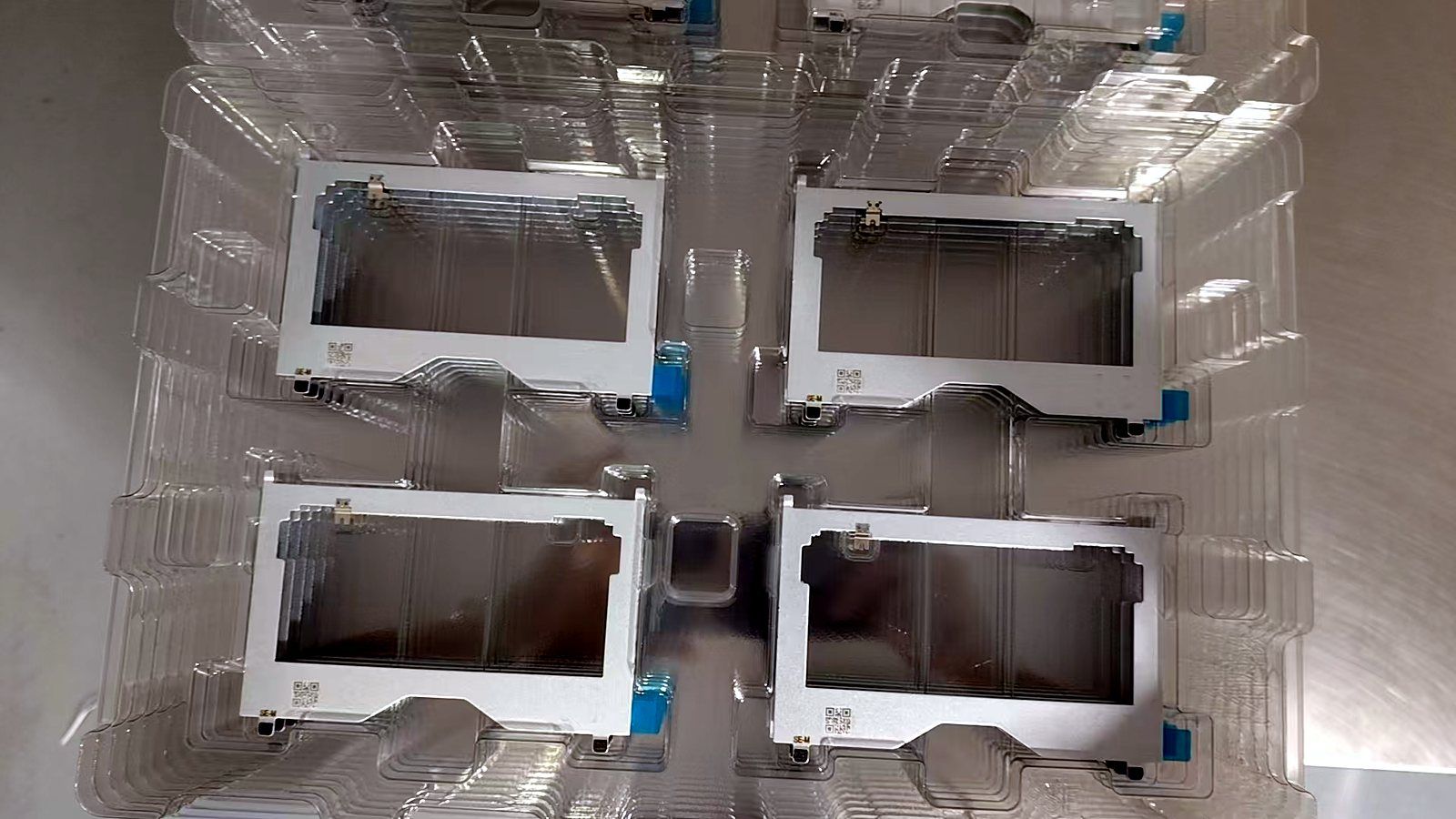
| Part types | Spring clips, grounding fingers, battery contacts, retaining clips |
|---|---|
| Materials | SUS304 and copper alloys |
| Tolerance | ±0.02 mm |
| Paired springs | Wire 0.2–2.0 mm on 6 CNC spring machines |
| Minimum order | 1,000 pcs |
A spring contact is specified by force at working deflection, not just by shape. Give us the target force, deflection and cycle requirement with the drawing; we check force on samples with push-pull gauges before production.
“Set” is the permanent loss of height after the contact is pressed. It happens when the bending stress exceeds the material’s elastic limit. A design that looks right in CAD can still take a set on first assembly, which lowers the contact force for the rest of the product’s life.
For a straight cantilever finger of width b, thickness t and free length L, standard beam theory gives a first estimate. Force at deflection δ is F = E·b·t³·δ / (4·L³), and the peak bending stress at the root is σ = 3·E·t·δ / (2·L²), where E is the elastic modulus of the material.
Two things follow. Force rises with the cube of thickness, so a small change in strip thickness changes force a lot. Stress rises with deflection and falls with the square of length, so a longer finger is the easiest way to avoid set. Formed shapes, dimples and preloads need FEA or sample testing, which is why we confirm force on samples.
| Material | Strength | Conductivity | Notes |
|---|---|---|---|
| SUS304 (spring tempers) | High | Low | Grounding fingers, retaining clips; in regular production |
| SUS301 spring stainless | Higher | Low | Higher-stress clips; quoted on request |
| C7701 nickel silver | Good | Low | Corrosion-resistant contacts; in regular production |
| C5191 phosphor bronze | Good | Moderate | Battery and signal contacts; quoted on request |
Battery contacts usually pair a stamped plate or clip with a conical or cylindrical coil spring. Because we run stamping presses and spring machines in the same factory, both parts can be sampled together and checked as a set for height and force.
Grounding fingers for enclosures and PCBs are usually stainless or nickel silver, sometimes plated at the contact point. Plating is done by qualified partners and should be specified with thickness on the drawing.
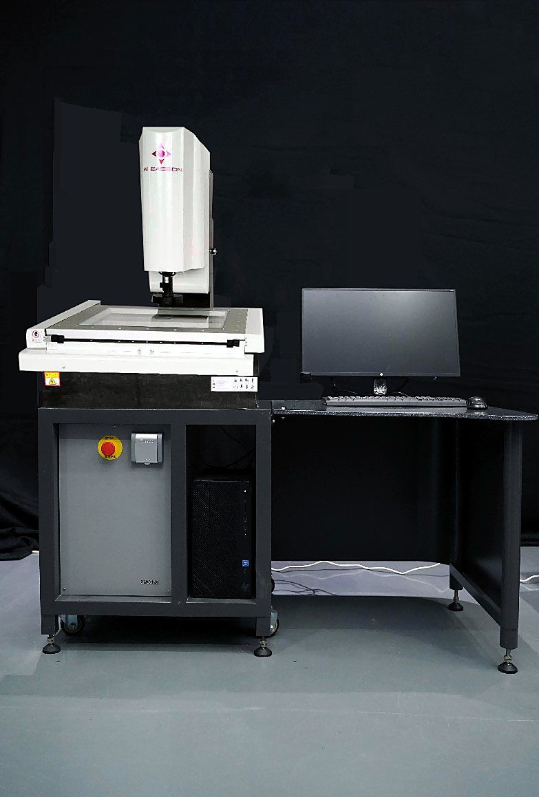
Dimensions are measured on a vision measuring system at first article and by AQL sampling on each lot, with automated optical inspection on critical features. Force at the working height is checked with push-pull gauges. Cycle testing requirements are agreed per project.
A drawing with material and thickness, the working deflection and target force at that deflection, plating, and annual volume.
With push-pull gauges at the working height, on samples before production and on production lots.
Yes. We coil 0.2–2.0 mm wire on six CNC spring machines and can ship both parts together.
Usually because it was deflected beyond its elastic limit and took a permanent set. A longer finger, lower deflection or stronger temper usually fixes it.
1,000 pieces. Sample cost and lead time are confirmed per project in the quote.
Custom compression, extension and torsion springs and wire forms, 0.2–2.0 mm wire, on 6 CNC spring machines. 2M+ pcs/month, MOQ 1,000.
Straight, conical and variable-pitch compression springs, 0.2–2.0 mm wire.
Copper-alloy terminals, lugs and contacts, loose or on carrier strip.
Progressive-die metal stamping in Suzhou: shielding cans, terminals, spring clips. 13 presses 60–250 T, ±0.02 mm, MOQ 1,000 pcs, ISO 9001.
Austenitic stainless for corrosion-resistant stamped parts and enclosures.
Solderable, springy copper-nickel-zinc alloy for shields and contacts.
Annual volume and your tightest tolerance help us quote tooling and unit price accurately the first time.