Send your drawing. Get a quote in 1 business day.
Annual volume and your tightest tolerance help us quote tooling and unit price accurately the first time.
Sierxi stamps custom board-level EMI and RF shielding cans, frames and snap-on covers on progressive dies in Suzhou. We work in 0.15–0.3 mm C7701 nickel silver, SPCC, SGCC and SUS304, hold ±0.02 mm on flatness-critical features, measure solder-flange coplanarity on every lot and quote from 1,000 pieces.
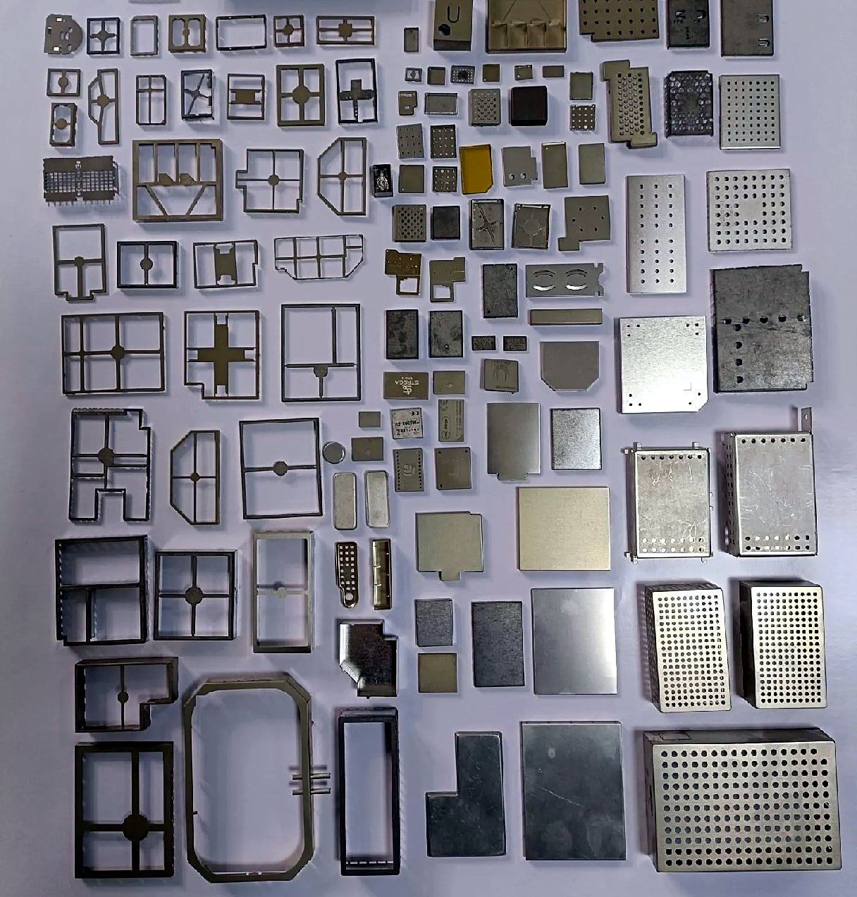
| Part types | One-piece cans, two-piece frame + cover, fences, perforated covers |
|---|---|
| Materials | C7701 nickel silver, SPCC, SGCC, SUS304 |
| Typical thickness | 0.15–0.3 mm |
| Tolerance | ±0.02 mm on critical features |
| Tooling | Progressive dies with in-die forming |
| Minimum order | 1,000 pcs |
A one-piece can is cheapest and is soldered straight onto the board. A two-piece design — a soldered frame plus a snap-on cover — lets you rework or inspect the components underneath, at the cost of a second die.
Send us the PCB footprint and component heights and we will suggest the layout, including pick-and-place pads, vent holes and corner reliefs.
| One-piece can | Two-piece frame + cover | |
|---|---|---|
| Tooling | One die | Two dies |
| Unit cost | Lowest | Higher (two parts) |
| Rework under the shield | Can must be desoldered | Cover snaps off |
| Height | Lowest profile | Slightly taller where cover overlaps frame |
| Typical use | Stable, mature designs | Boards that need test access or rework |
These are typical guidelines for stamped board-level shields. Final values depend on your reflow process, component heights and the frequencies you need to block, so treat them as a starting point for design review.
| Material | Solderability | Why choose it |
|---|---|---|
| C7701 nickel silver | Good without plating | Solders well, good shielding, stays bright |
| SPCC cold-rolled steel | Needs tin or nickel plating (partner) | Low cost, magnetic — useful for low-frequency shielding |
| SGCC galvanized steel | Limited; usually mechanically fixed | Corrosion-resistant covers and fences |
| SUS304 stainless steel | Difficult; needs plating or special flux | Strong thin covers that resist denting |
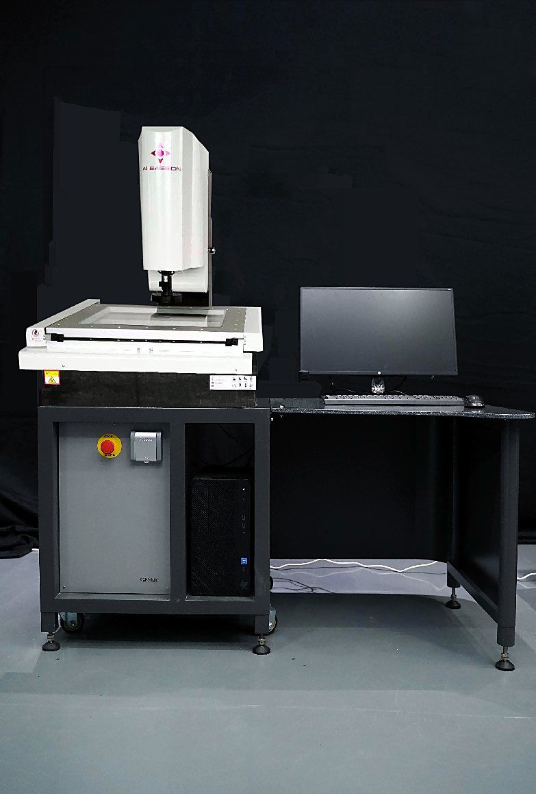
Shielding cans fail at reflow when the solder edge is not flat. We measure coplanarity of the solder flange on a vision measuring system at first article and on every lot, and include the results in the dimensional report.
Flatness is designed into the die rather than corrected afterwards: strip layout, forming sequence and the final restrike station are reviewed with our toolroom partner before the die is built.
Stamped shields cover RF modules, wireless chipsets, processors, memory and switching power stages on boards for consumer electronics, networking equipment, industrial controllers and test instruments. The aim is the same in each case: keep noise from one circuit away from its neighbours and help the product pass EMC testing without a full metal housing.
The shield is only part of the solution. Its performance also depends on the ground pad ring on the PCB, via spacing along that ring and the gaps between solder joints, so the can and the footprint should be reviewed together.
Thin cans dent and nest easily, so packing is chosen per project. Options include formed trays, anti-static bags and tape and reel for automatic placement. Tell us your placement machine and reel requirements with the RFQ and we confirm the packing in the quote. Freight is quoted per destination.
Tell us your packaging requirement with the RFQ. We confirm packing options, including trays and tape and reel, per project.
A drawing of the can is enough to quote. A footprint and component heights help us check the design before tooling.
C7701 nickel silver is a common choice because it solders well without plating. Tin-plated steel is cheaper per kilogram but adds a plating step.
Thin cans are normally produced on a progressive die. For early prototypes, ask us — we confirm the most practical sample route per project in the quote.
On a vision measuring system at first article and on every production lot. Results are included in the dimensional report.
1,000 pieces per part number.
Progressive-die metal stamping in Suzhou: shielding cans, terminals, spring clips. 13 presses 60–250 T, ±0.02 mm, MOQ 1,000 pcs, ISO 9001.
Multi-station dies fed from coil for high-volume small parts.
Copper-alloy terminals, lugs and contacts, loose or on carrier strip.
Solderable, springy copper-nickel-zinc alloy for shields and contacts.
Shielding cans, terminals, contacts, brackets and springs for electronics.
Equivalent grades for SPCC, SGCC, SUS304, A5052 and C7701 across JIS, ASTM/UNS, EN and Chinese GB standards, for stamping and sheet metal.
Annual volume and your tightest tolerance help us quote tooling and unit price accurately the first time.