Send your drawing. Get a quote in 1 business day.
Annual volume and your tightest tolerance help us quote tooling and unit price accurately the first time.
Sierxi makes custom connector terminals, contacts, lugs and bus parts from copper-alloy and steel strip on progressive dies in Suzhou. Parts can be supplied loose or on carrier strip, and insert molded into plastic housings on our 180-ton injection machines. Tolerances to ±0.02 mm, from 1,000 pieces.
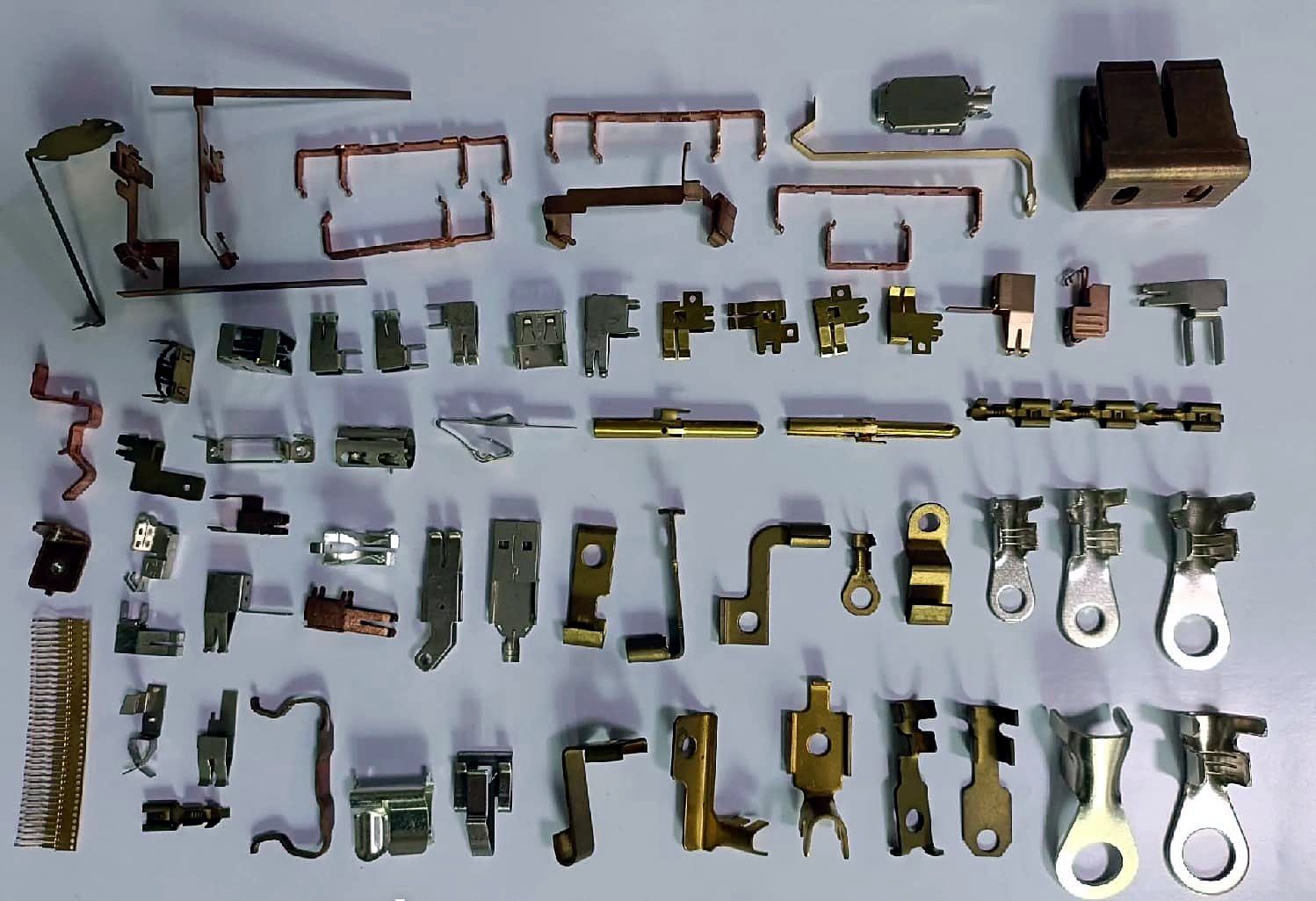
| Part types | Terminals, contacts, lugs, bus bars, solder tabs |
|---|---|
| Materials | Copper alloys incl. C7701 nickel silver, steel, stainless |
| Supply form | Loose or on carrier strip |
| Secondary | Insert molding (180 T), plating via partners |
| Tolerance | ±0.02 mm |
| Minimum order | 1,000 pcs |
Terminal material is a trade-off between conductivity, spring properties, formability and cost. The values below are typical published figures for annealed or common tempers and vary with temper; check the mill certificate for your exact grade. C7701 nickel silver is in regular production with us; other alloys are quoted on request.
| Alloy (JIS / UNS) | Conductivity, typical | Spring properties | Typical use |
|---|---|---|---|
| C1100 tough-pitch copper | ~100% IACS | Poor | Bus bars, high-current lugs |
| C2680 brass | ~25–28% IACS | Moderate | Low-cost terminals, solder tabs |
| C5191 phosphor bronze | ~13–15% IACS | Good | Connector contacts with mating cycles |
| C7701 nickel silver | Low, single-digit % IACS | Good, corrosion resistant | Contacts, solderable shields, clips |
Tin, nickel, silver and gold plating are done by qualified plating partners. The right thickness depends on mating cycles, current and environment. The ranges below are common industry starting points, not our specification — put the value you need on the drawing.
| Plating | Typical thickness | When it is used |
|---|---|---|
| Nickel underplate | ~1–3 µm | Diffusion barrier under tin or gold |
| Bright or matte tin | ~1–5 µm | Solderable, low-cycle contacts |
| Gold flash | ~0.05–0.1 µm | Corrosion protection, few mating cycles |
| Hard gold | ~0.4–1.3 µm | Contacts with many mating cycles |
| Silver | ~2–5 µm | Power contacts and higher current |
When a terminal needs a plastic body, we stamp it and mold it in-house on Sumitomo and Tongyang 180-ton injection machines, so one supplier owns both the metal and the plastic tolerance. Molds are built by partner toolmakers.
For insert molding, keep the terminal on its carrier strip into the mold where possible, add locking features (holes or notches) inside the plastic, and leave enough plastic wall around the metal to avoid cracking.

Loose terminals suit manual assembly and low volumes. Reeled carrier strip suits automatic crimping, insertion or insert molding and protects contacts from tangling in transit. Reel size, interleaf paper and splice rules are confirmed per project.
| Terminal type | How it connects | What matters on the drawing |
|---|---|---|
| Crimp terminal | Wire and insulation barrels crimped onto the wire | Barrel width, wall thickness, serrations; crimp height is set by your applicator |
| Solder terminal / tab | Soldered to a PCB or wire | Solderable plating, pin width and true position |
| Press-fit pin | Pressed into a plated PCB hole | Compliant zone geometry and hole size range |
| Ring or fork lug | Clamped under a screw or stud | Hole size, contact area and current rating |
We run an ISO 9001:2015 quality system. First articles from a new die are measured in full on a vision measuring system. Production lots are inspected by AQL sampling, and features you mark as critical — contact height, pin width or position — are checked at 100% by automated optical inspection. A dimensional report and material certificates (mill test certificates) ship with every lot on request.
Tell us the plating spec and thickness on the drawing. If you need RoHS or REACH declarations for the finished part, ask with your RFQ and we will confirm what documentation can be supplied for that material and plating.
Yes, terminals can be supplied on carrier strip. Reel size and packing details are confirmed per project.
No. Plating is done by qualified plating partners; we specify, receive and inspect the plated parts.
Pure copper such as C1100 gives the highest conductivity. Brass or nickel silver trade conductivity for strength or corrosion resistance.
Yes. We insert mold in-house on 180-ton machines; the mold is built by a partner toolmaker.
On a vision measuring system at first article and by AQL sampling on every lot, with automated optical inspection on critical features.
1,000 pieces. Sample cost and lead time are confirmed per project in the quote.
Progressive-die metal stamping in Suzhou: shielding cans, terminals, spring clips. 13 presses 60–250 T, ±0.02 mm, MOQ 1,000 pcs, ISO 9001.
Flat springs, grounding fingers and battery contacts.
Multi-station dies fed from coil for high-volume small parts.
Solderable, springy copper-nickel-zinc alloy for shields and contacts.
Shielding cans, terminals, contacts, brackets and springs for electronics.
Custom compression, extension and torsion springs and wire forms, 0.2–2.0 mm wire, on 6 CNC spring machines. 2M+ pcs/month, MOQ 1,000.
Annual volume and your tightest tolerance help us quote tooling and unit price accurately the first time.