Send your drawing. Get a quote in 1 business day.
Include your annual volume and tightest tolerance, and we can quote tooling and unit price right the first time.
Sheet metal design for manufacturability means sizing flanges, bend radii, holes and reliefs so parts can be cut, bent and finished without extra tooling or rework. Most rules scale with material thickness (T): flanges at least 4T, inside bend radius about 1T, holes at least 2T from a bend. Check each against your supplier’s tooling.
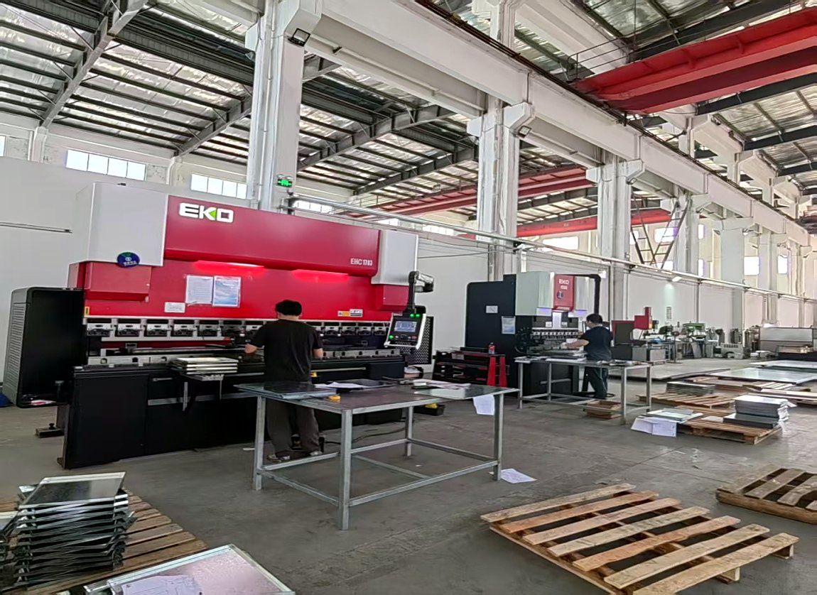
The values below are typical rules of thumb for laser-cut and press-brake-formed parts in mild steel, stainless steel and aluminum. They are expressed in multiples of material thickness (T) so they scale with your design. Actual limits depend on the supplier’s punches, dies and tooling, so treat them as a starting point and ask for a DFM review before you release the drawing.
Stamped parts follow similar logic but the die can do more (and some things less). Our stamping guides cover those cases.
A flange must be long enough to rest on the V-die during bending. A typical minimum flange length is about 4T, or the V-die opening ÷ 2 plus the bend radius, whichever is larger. For 1.5 mm steel, plan on at least 6 mm. Shorter flanges need special tooling or a different method and often bend unevenly.
Use one inside radius for all bends on the part when you can. It allows one tool set and keeps the flat pattern consistent. Specify the radius the supplier’s standard tooling produces rather than an arbitrary number.
| Material | Typical minimum inside radius | Notes |
|---|---|---|
| Mild steel (SPCC, DC01) | 1T | 0.5T possible on thin gauge |
| Galvanized steel (SGCC) | 1T | Tight radii can crack the zinc layer |
| Stainless steel (SUS304) | 1–1.5T | Higher springback; allow more angle tolerance |
| Aluminum 5052-H32 | 1–1.5T | Bends well; bend across the grain where possible |
| Aluminum 6061-T6 | 2–3T or more | Prone to cracking; consider a softer temper |
For laser cutting, a hole diameter of at least 1T is a safe rule for steel, with a practical floor around 0.5–1 mm on thin sheet. Smaller holes may be possible but lose roundness and can fill with dross. For stamping (punching), keep hole diameter at least 1T for steel and 1.5–2T for stainless steel to protect the punch. Holes that will be tapped or receive hardware must follow the hardware maker’s tables.
Add a relief cut where a bend meets an uncut edge or another bend. Without it, material tears or bulges at the corner. A typical relief is at least T wide and extends past the bend by the inside radius plus T. For boxes, add corner reliefs (round or square) where two flanges meet so the corners close cleanly before welding.
Yes, for tight radii and harder materials. Bending across the rolling direction is less likely to crack than bending parallel to it. If a part has a tight bend in stainless steel or aluminum, note the preferred grain direction on the drawing. Note that it may reduce nesting efficiency and raise material cost slightly.
Each bend adds variation. A dimension measured across three bends carries the cut tolerance plus the tolerance of each bend. Typical bend tolerances are ±0.2–0.5 mm per bend depending on length and thickness, so a feature four bends away from its datum will drift more than the drawing may expect.
Dimension critical features from the same face or bend, close to each other, and avoid chaining dimensions across multiple bends. Use a general tolerance standard for everything else: ISO 2768-m is common for sheet parts, and JIS B 0408 gives separate tables for blanked and bent dimensions. See our JIS B 0408 tolerance guide for the full tables.
Powder coat typically adds 60–120 μm per surface. That changes fits on slots, tabs and holes. Enlarge holes for fasteners, mask threads and mating faces, and specify which surfaces need masking. If dimensions are critical after coating, state on the drawing whether a dimension applies before or after coating.
The flat pattern depends on the bend allowance, which depends on the K-factor (the position of the neutral axis). Typical K-factors range from about 0.3 to 0.5 depending on material, radius and tooling. Your CAD default may not match the supplier’s press brake.
Send your flat pattern for reference, but expect the supplier to recalculate it with their own bend deduction tables. Dimension the formed part, not the flat, unless the flat is what matters.
| Check | Typical rule | Done? |
|---|---|---|
| Flange length | ≥ 4T | ☐ |
| Inside bend radius | ≈ 1T steel; larger for hard aluminum | ☐ |
| Single radius on all bends | Yes, where possible | ☐ |
| Hole to edge | ≥ 1–1.5T | ☐ |
| Hole to bend | ≥ 2T + bend radius | ☐ |
| Minimum hole diameter | ≥ 1T | ☐ |
| Bend relief at corners | Width ≥ T; length ≥ radius + T | ☐ |
| Grain direction noted for tight bends | Across grain | ☐ |
| Hardware per maker’s tables | Hole size, edge distance, hardness | ☐ |
| Weld joints self-locating | Tabs and slots, tight gaps | ☐ |
| Critical dimensions from one datum | Avoid chains across bends | ☐ |
| General tolerance standard stated | ISO 2768 or JIS B 0408 | ☐ |
| Coating allowance and masking | 60–120 μm per side typical | ☐ |
| Files | STEP + DXF + PDF | ☐ |
Typically about 4 times the material thickness, depending on the V-die opening. For 1.5 mm steel, plan on at least 6 mm.
About 1T for mild steel and 5052 aluminum, 1–1.5T for stainless steel, and 2–3T or more for 6061-T6. Use one radius for all bends where possible.
Typically at least 2T plus the inside bend radius from the hole edge to the bend. Closer holes deform unless they are cut after bending.
ISO 2768-m is common internationally. JIS B 0408 is common on Japanese drawings and has separate tables for blanked and bent dimensions.
Yes, as a DXF for reference, together with a STEP model and a PDF drawing. The supplier will recalculate the flat pattern for its own tooling.
Yes. Send your STEP and PDF drawing with your quote request and we will flag features that add cost or risk.
JIS B 0408 general tolerance tables for blanked and bent or drawn metal parts, grades A, B and C, and how to call them out on your drawing.
Custom sheet metal fabrication in Suzhou: enclosures and cabinets laser cut, bent and welded in-house. Sheet to 1500 × 3000 mm and 20 mm, bends to 3 m.
Low-distortion laser welding of enclosures, frames and stamped assemblies.
Tool-free prototypes and small batches, with a path to stamping.
Control boxes, cabinets and automation-equipment housings.
Include your annual volume and tightest tolerance, and we can quote tooling and unit price right the first time.